Audio Amplifiers

LM386 Audio Amplifier with Gain 20

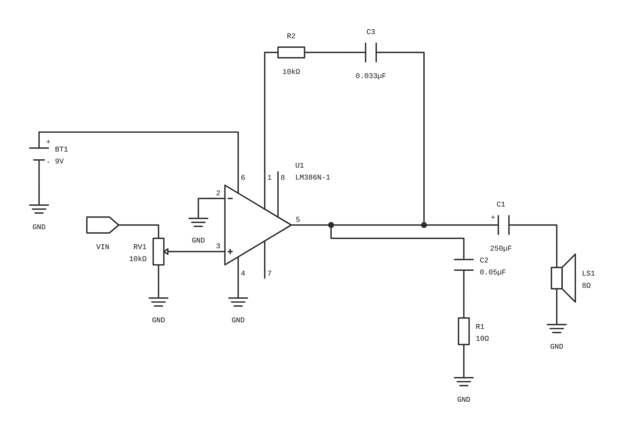
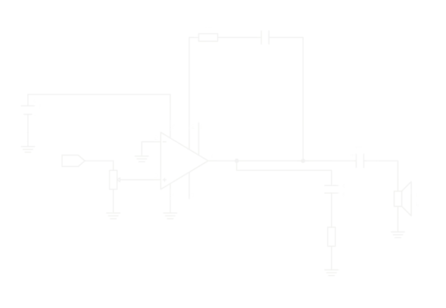
The minimum-parts speaker amplifier from the TI LM386 datasheet: a volume potentiometer, the LM386 at its internal gain of 20, an output capacitor and an RC network driving an 8 Ω speaker from a 9 V battery.

Operating Supply Voltage
9V battery as drawn; LM386N-1 operating range 4 V – 12 V (TI §6.5); design table 5 V – 12 V (TI Table 9-1)
Components
7
Formulas
3
Gotchas
4
Open in Web CAD
Verified source

Schematic workbench

LM386 Audio Amplifier, Gain 20Exported from CircuitBase+-BT19VRV110kΩ23561847U1LM386N-1+C1250µFC20.05µFR110ΩLS18ΩGNDVINGNDGNDGNDGNDGND

Circuit overview

Operating Supply Voltage
9V battery as drawn; LM386N-1 operating range 4 V – 12 V (TI §6.5); design table 5 V – 12 V (TI Table 9-1)
Components
7
Formulas
3
Gotchas
4

Click any component in the schematic above to inspect its electrical ratings, function, and connections.

Circuit overview

This is Figure 9-1 of the Texas Instruments LM386 datasheet (SNAS545D), the lowest part-count way to drive a speaker with the LM386. The amplifier's gain is fixed internally at 20, so no feedback parts are needed; the inputs are referenced to ground, so the signal can go straight to pin 3 through the volume control; and the output biases itself to half the supply, so a single capacitor couples it to the speaker. A 9 V battery is drawn as the supply; any supply within the datasheet range of 5 V to 12 V works the same way. TI notes that its application circuits are not part of the component specification and that the final design must be validated.

Key Technical Specifications

Operating Supply Voltage9V battery as drawn; LM386N-1 operating range 4 V – 12 V (TI §6.5); design table 5 V – 12 V (TI Table 9-1)
Voltage Gain20 (26 dB) with pins 1 and 8 open (TI §9.2.1.2.1)
Load8 Ω speaker; design table 4 Ω – 32 Ω (TI Table 9-1)
Output Power325 mW typical, 250 mW minimum at VS = 6 V, RL = 8 Ω, THD = 10% (LM386N-1); the datasheet does not specify LM386N-1 output power at 9 V
Quiescent Current4 mA typical, 8 mA maximum at VS = 6 V, VIN = 0 (TI §6.5)
Input Voltage at Pin 3−0.4 V to +0.4 V (absolute maximum and recommended range)
Low-Frequency Corner≈ 80 Hz, calculated from C1 = 250 µF and an 8 Ω load; not measured

Theory of Operation & Working Principle

01

Input and volume

The input signal VIN goes to the top of RV1, a 10 kΩ potentiometer whose other end is grounded. The wiper picks off part of the signal and feeds it to pin 3 (+INPUT). Pin 2 (−INPUT) is connected to ground. Both inputs are biased to ground inside the LM386 through 50 kΩ resistors. Figure 9-1 draws no input coupling capacitor; TI notes that adding one removes input offset problems entirely. Keep the signal at pin 3 within −0.4 V to +0.4 V, the absolute maximum input voltage; turning RV1 down is how this circuit does that.
02

Fixed gain of 20

Pins 1 and 8 are left open. In that state the internal 1.35 kΩ resistor sets the voltage gain to 20, which is 26 dB:

FORMULA & CALCULATION
AV = 20, 20\log10(20) ≈ 26 dB

A capacitor from pin 1 to pin 8 would raise the gain to 200 (46 dB); this circuit does not use it.

03

Output bias and coupling to the speaker

The output stage biases itself to about half the supply voltage, about 4.5 V with a 9 V battery. C1 blocks that DC level so no steady current flows through the speaker, and passes the audio signal. Its positive terminal faces pin 5. Together with the 8 Ω speaker it forms a high-pass filter with a calculated corner frequency of about 80 Hz:

FORMULA & CALCULATION
fc = (1) / (2\pi RL C1) = (1) / (2\pi × 8\,Ω × 250\,µF) ≈ 80 Hz

Frequencies below the corner reach the speaker attenuated.

04

RC network on the output

C2 (0.05 µF) and R1 (10 Ω) in series run from pin 5 to ground. TI places such a network on the output in most application circuits of the datasheet without describing its purpose. Such a series RC is commonly called a Zobel or Boucherot network: at high frequencies, where the speaker coil's impedance rises, it gives the amplifier a load of about 10 Ω, which helps keep it stable.

05

Supply

The LM386N-1 operates from 4 V to 12 V, and draws 4 mA typical (8 mA maximum) with no signal at 6 V. TI recommends a capacitor to GND close to pin 6; the datasheet does not give its value and Figure 9-1 does not draw it.

Design Equations & Calculations

Voltage Gain

AV(dB) = 20log10(AV) = 20log10(20) ≈ 26 dB

Gain set by the internal 1.35 kΩ resistor with pins 1 and 8 open.

SymbolParameterTypical value
AVVoltage gain (ratio)20V/V

Output Coupling Corner Frequency

fc = 12π RL C1

Frequency below which C1 and the speaker attenuate the signal (−3 dB), treating the speaker as a pure 8 Ω resistance.

SymbolParameterTypical value
RLSpeaker impedance8Ω
C1Output coupling capacitor250µF
fcCorner frequency (calculated)80Hz

Output Bias Voltage

VOUT(DC) ≈ VS2

The output biases itself to about half the supply voltage; C1 blocks this DC level from the speaker.

SymbolParameterTypical value
VSSupply voltage9V
VOUT(DC)Output bias voltage4.5V

Bill of Materials (BOM)

Every part needed to build this circuit. Select a reference designator to inspect it on the schematic.

RefDesComponentValue / ratingPackageRole in circuitReference
Low-Voltage Audio Power Amplifier

TI LM386N-1/NOPB. LM386N-3 and LM386N-4 share the pinout but have different supply and output-power ratings.

LM386N-1PDIP-8Power amplifier, gain 20Low-Voltage Audio Power Amplifier pinout & datasheet
Rotary Potentiometer10kΩPanel / PCB mountVolume control and input attenuator—
Aluminium Electrolytic Capacitor

Datasheet value. 220 µF is the nearest common value and moves the calculated corner to about 90 Hz. Voltage rating above the supply; + towards pin 5.

250µFRadialOutput coupling to the speaker—
Ceramic or Film Capacitor

Datasheet value; 47 nF is the nearest common value.

0.05µFRadial / 0805Output RC network—
Resistor 1/4 W10ΩAxial / 0805Output RC network—
Loudspeaker

4 Ω to 32 Ω per TI Table 9-1.

8ΩWiredLoad—
9 V Battery

Any supply from 5 V to 12 V (TI Table 9-1).

9VPP3 / 6LR61Supply—

Practical Applications & Target Domains

AM-FM radio amplifiers
Intercoms
TV sound systems
Battery-powered speaker output for portable audio projects

Critical Design Traps & Engineering Gotchas

Traps found in real builds, with the fix for each.

Critical

Overdriving the Input

The absolute maximum input voltage is ±0.4 V. A headphone or line-level signal can be larger; fed straight to pin 3 it can exceed that rating, and the output clips well before the input reaches it.

Mitigation

Keep RV1 between the source and pin 3 as drawn and start with the volume turned down; keep the signal at pin 3 within ±0.4 V.

Warning

Missing Supply Decoupling

Figure 9-1 draws no capacitor on the supply, but TI recommends one close to pin 6. Without it, long battery leads and supply ripple reach the output as hum or instability.

Mitigation

Add a capacitor from pin 6 to GND right next to the IC (the datasheet does not give a value) and keep the speaker leads short (TI §10, §11.1).

Warning

C1 Fitted Backwards

Pin 5 sits at about half the supply, so C1 has a steady DC voltage across it. An electrolytic fitted the wrong way round is reverse-biased.

Mitigation

Fit C1 with its positive terminal towards pin 5 and the negative terminal towards the speaker, and use a voltage rating above the supply voltage.

Note

Expecting More Gain

With pins 1 and 8 open the gain is only 20. A weak source such as a microphone will sound quiet.

Mitigation

For a gain of 200, connect a 10 µF capacitor from pin 1 to pin 8 (TI Figure 9-3), and bypass or ground the unused input as TI §9.2.1.2.2 requires at high gain.

Primary sources

Help keep this page accurate

Built, simulated or reviewed this circuit? Confirm it, or report a part, value or connection that is wrong.

Opens a public form on GitHub with this page already filled in; a free GitHub account is needed. How reports and confirmations work

HTML snippet

<iframe src="https://circuitbase.tech/embed/schematic/lm386-audio-amplifier-gain-20?theme=paper" width="100%" height="500" frameborder="0" loading="lazy" style="border: 1px solid #e5e7eb; border-radius: 6px; max-width: 100%;" title="LM386 Audio Amplifier with Gain 20 — CircuitBase Interactive Schematic"></iframe>