
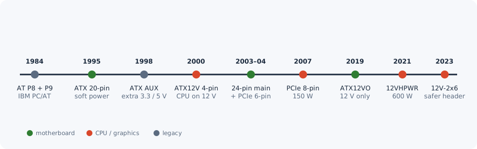
Every cable that leaves a PC power supply ends in a different plug, and every one of them was added to solve a specific problem: a processor that needed more current, a graphics card that outgrew its slot, a drive that had to be swapped while running. This guide shows how to recognise each plug, what it powers, how much power it may carry and what tends to go wrong with it.
Pin numbers and ratings come from Intel's ATX design guides, the IBM PC/AT Technical Reference and connector makers' documents. Where something comes from a review, a news story or a forum, we say so. Every connector links to its interactive pinout in the CircuitBase connector catalogue.
Quick identification guide
| Plug | How to recognise it | Powers | Limit |
|---|---|---|---|
| ATX 24-pin | The widest plug, 2 rows of 12, often split 20+4 | Motherboard | — |
| CPU 4-pin (P4) | 2 × 2, two yellow and two black wires | Processor | — |
| CPU 8-pin (EPS12V) | 2 × 4, often split 4+4, labelled CPU | Processor | — |
| PCIe 6-pin | 2 × 3, labelled PCI-E | Graphics card | 75 W |
| PCIe 8-pin (6+2) | 2 × 4, a 6-pin block plus a clip-on 2-pin part | Graphics card | 150 W |
| 12V-2x6 / 12VHPWR | Small 2 × 6 plug with 4 tiny pins underneath | Graphics card | 600 W |
| SATA power | Flat, L-shaped slot, 15 thin contacts | Drives, fan hubs | — |
| Peripheral 4-pin ("Molex") | White, 4 round pins in a row | Pumps, fans, old drives | — |
| Floppy 4-pin ("Berg") | Small white plug, 4 contacts | Floppy drives | — |
| ATX12VO 10-pin | 2 × 5, on 12 V-only systems | Motherboard | 216–288 W |
| ATX AUX 6-pin | 1 × 6, on late-1990s supplies | Extra 3.3 V / 5 V | — |
| AT P8 + P9 | Two flat 6-pin plugs side by side | Whole board (pre-ATX) | — |
The supply itself is fed by an IEC C13 mains cord; everything that comes out of it is low-voltage DC.
ATX 24-pin: the motherboard plug
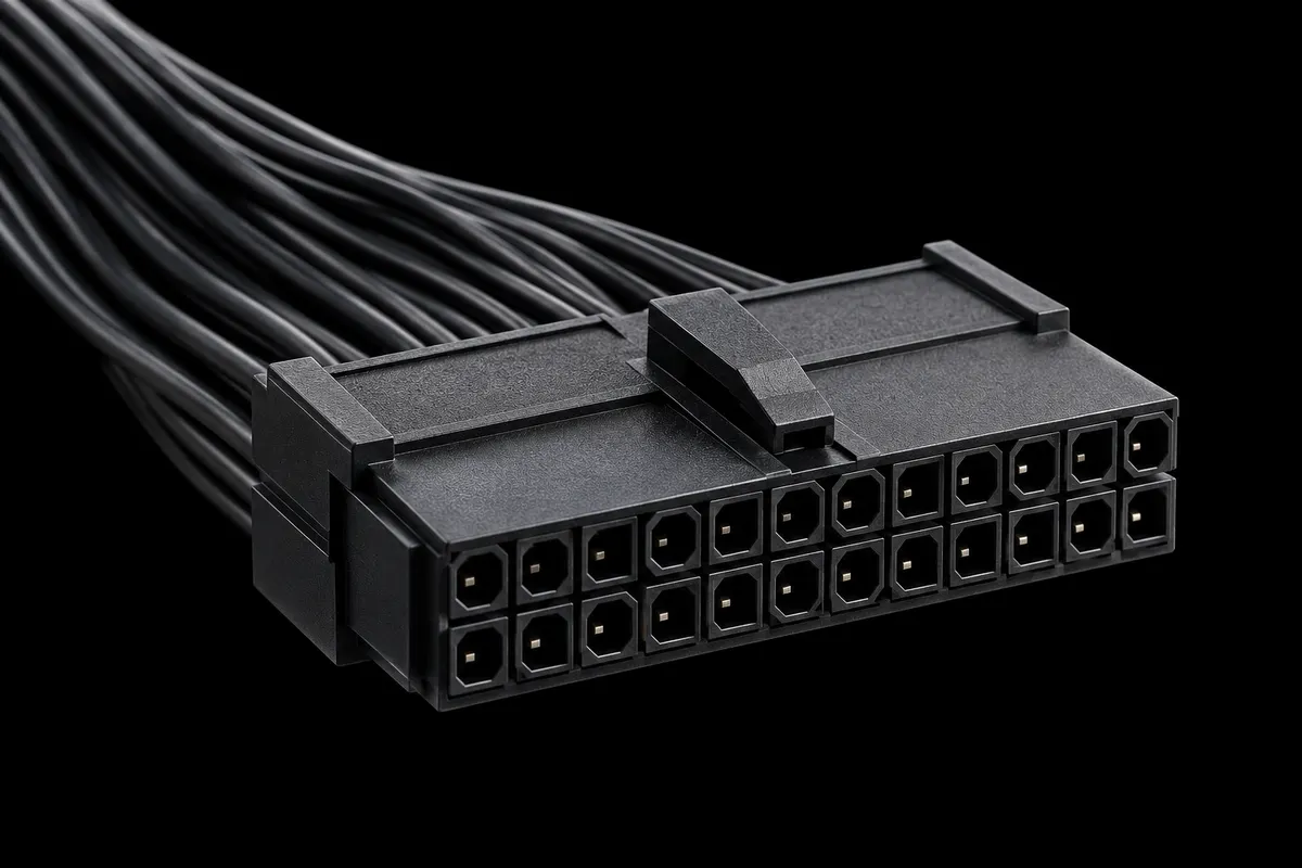
The biggest plug feeds everything on the motherboard except the processor: chipset, memory, PCIe slots, USB.
What is on it (Intel ATX 3.0 design guide):
- four +3.3 V, five +5 V and two +12 V contacts, plus one −12 V
- +5VSB (purple): standby power that stays on while the PC is "off"
- PS_ON# (green): the switch line, the motherboard pulls it to ground to start the supply
- PWR_OK (gray): tells the board the voltages are stable
- grounds, and one Reserved position
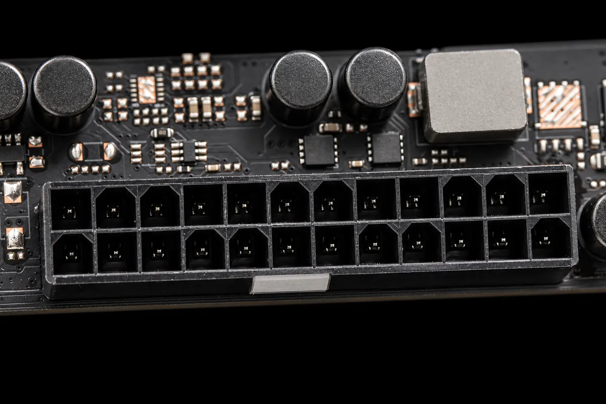
Why some cables are 20+4. The plug started with 20 contacts in 1995. Intel's ATX 2.01 says it "combines all four of these connectors into a single 20-pin connector". Four more (+12 V, +3.3 V, +5 V, ground) arrived with ATX12V 2.0 for PCI Express slots, and the split plug still fits older boards.
Did you know? Pin 20 is empty on purpose. On the 20-pin original that spot carried −5 V on a white wire (ATX 2.03); later supplies dropped −5 V and left the hole.
Did you know? Pin 13 often has two wires: orange +3.3 V and a thin brown sense wire. Intel even specifies 22 AWG for that pin "for the +3.3 V supply and sense return wires combined". The supply uses it to measure the voltage at the board.
CPU power: 4-pin and 8-pin
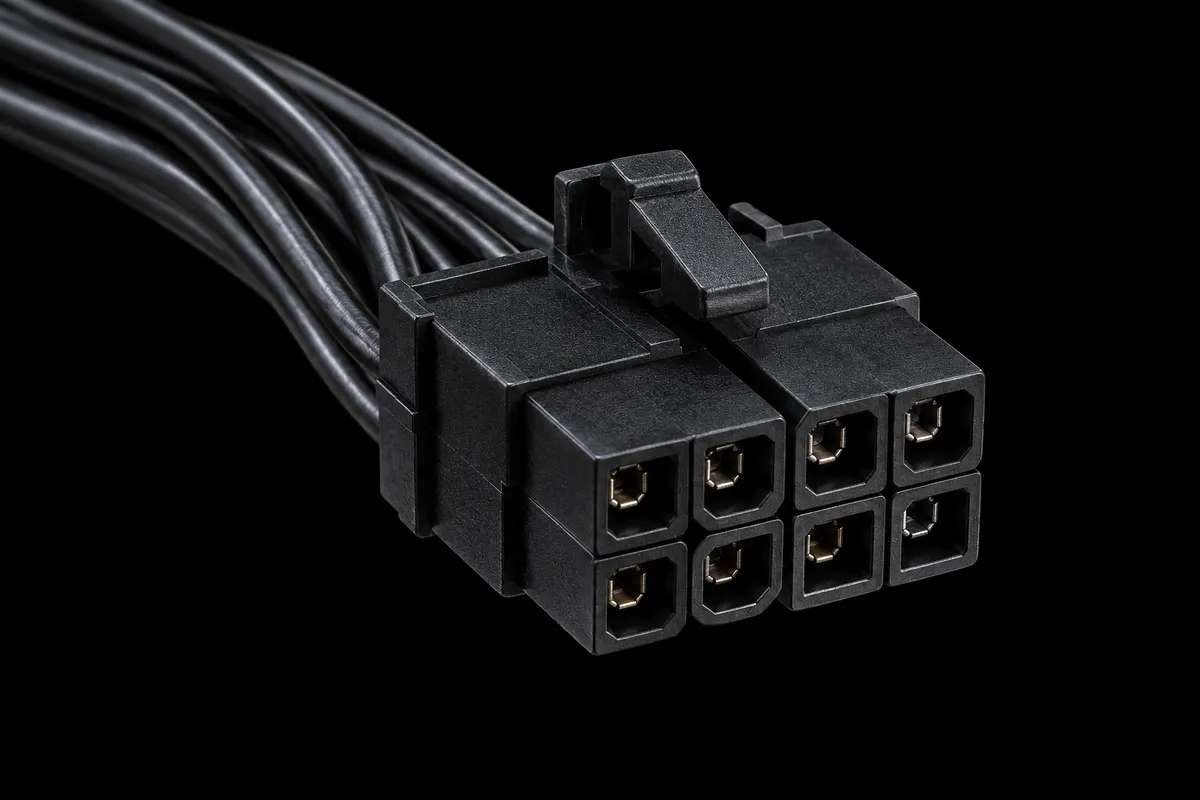
Around 2000 processors started to need more current than the main plug could give them, so Intel added a separate 12 V feed for the processor's voltage regulator.
| 4-pin (P4) | 8-pin (EPS12V) | |
|---|---|---|
| +12 V contacts | pins 3–4 | pins 5–8 |
| Ground | pins 1–2 | pins 1–4 |
| Where you see it | older and entry-level boards | almost every board today |
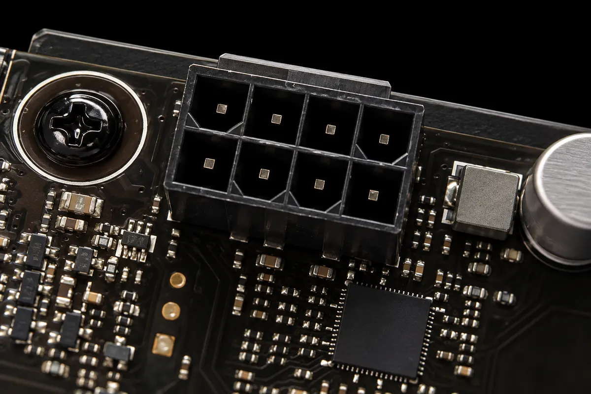
- Most supply cables split the 8-pin plug into 4+4, so one half still fits a 4-pin board.
- High-end boards often have two CPU sockets (8+8 or 8+4). Corsair says one CPU cable is usually enough outside extreme overclocking; follow your motherboard manual for which sockets must be connected.
- Builders on Reddit point out that the detachable half often has all four cavities rounded, so it fits either half of the socket.
Graphics cards: PCIe 6-pin and 8-pin
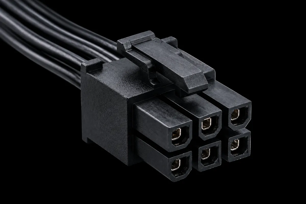
A PCIe x16 slot gives a graphics card 75 W. Cards that need more take it from these plugs. The surprise is in the pinout:
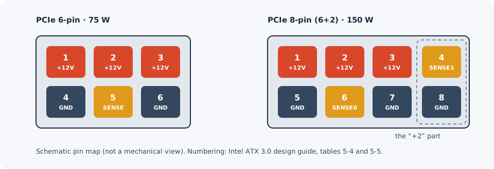
How the card knows what is plugged in (Intel ATX 3.0 design guide, table 5-6):
| SENSE1 (pin 4) | SENSE0 (pin 6) | Meaning |
|---|---|---|
| open | ground | 6-pin plug, up to 75 W |
| ground | ground | 8-pin plug, up to 150 W |
| open | open | nothing plugged in |
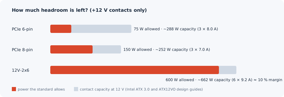
So why does doubling the power not need more wires? Because the standard leaves a lot of room. Intel rates the contacts at 8.0 A each in the 6-pin plug and 7.0 A in the 8-pin plug:
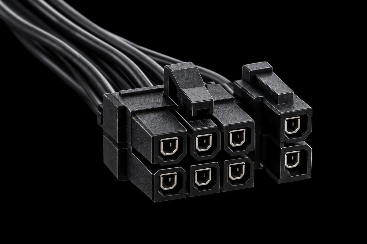
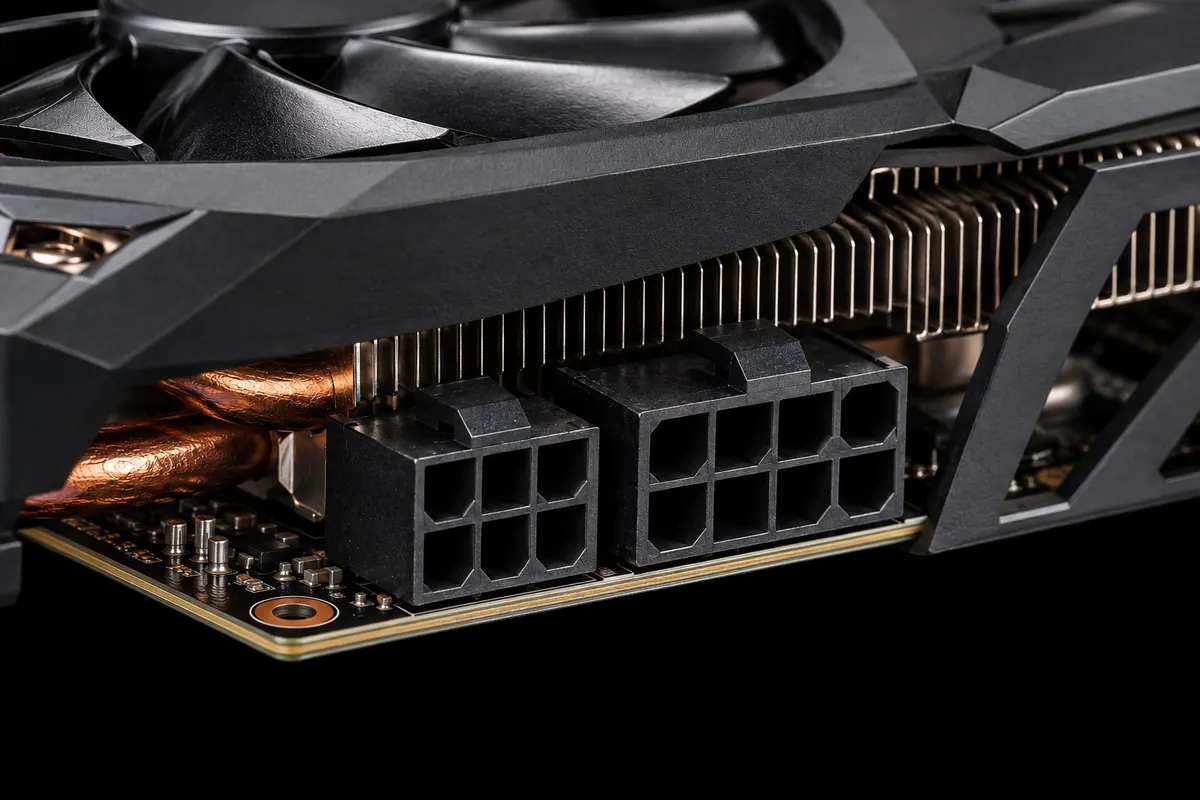
Tips from builders and cable makers (not from the standard):
- A 6+2 plug is just as good as a solid 8-pin one; the split only lets it fit 6-pin cards.
- Many supplies put two plugs on one cable ("pigtail"). For cards above 225 W, Seasonic recommends a separate PCIe cable for each socket; follow your card and supply makers' instructions.
Never swap CPU and graphics 8-pin plugs
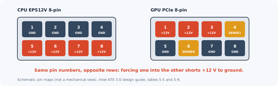
Both have 8 contacts and look almost the same. The housings are keyed differently, but users on Reddit's r/homelab report that only one or two cavity shapes differ and that a soft nylon plug can be forced in. If a plug needs force, stop and read the label: CPU or PCI-E.
The same mix-up catches people who buy used data-centre graphics cards: according to those discussions, NVIDIA's server cards such as the Tesla M40 take power through a CPU-style EPS socket.
12V-2x6 (12VHPWR): 600 W through one plug
Flagship graphics cards outgrew even three 8-pin plugs, so PCI-SIG introduced a single 16-pin connector in 2021: 12VHPWR. Its current version, 12V-2x6, is described in Intel's ATX12VO design guide (revision 2.11):
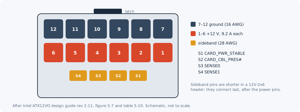
- 12 power contacts on a 3.0 mm pitch: six +12 V and six ground, on 16 AWG wire
- 4 small sideband contacts that talk to the card and the supply
- each power contact rated 9.2 A
The two SENSE pins set the card's power budget. This is the 12V-2x6 table (Intel ATX 3.0 design guide rev 2.1, table 3-6); the 0 W row is new in 12V-2x6:
| SENSE0 | SENSE1 | At power-up | After setup |
|---|---|---|---|
| ground | ground | 375 W | 600 W |
| open | ground | 225 W | 450 W |
| ground | open | 150 W | 300 W |
| shorted together | 100 W | 150 W | |
| open | open | 0 W | 0 W |
Why early plugs melted
With equal sharing, at 600 W each +12 V contact carries about 8.3 A against a 9.2 A rating, about 90 % of it. The 8-pin PCIe plug at its 150 W limit uses about 60 % of its 7.0 A rating.
- August 2022. According to Gamers Nexus, PCI-SIG warned its members after lab samples melted.
- From October 2022. Owners of new high-end cards report melted plugs. Gamers Nexus reproduces failures in its lab; Igor's Lab looks inside the adapters.
- November 2022. In its update on the reports it was investigating, NVIDIA said that "a common issue is that connectors are not fully plugged into the graphics card". Less contact area means more heat.
- Later. Gamers Nexus covers CableMod's recall of its angled adapters.
What 12V-2x6 changed (2023)
Intel's guide describes the fix in one line: "the power pins have been lengthened and the sideband pins have been shortened in the PCB Header".
- The power pins touch first; the shorter sense pins connect only after the power pins are sufficiently mated.
- A new 0 W state: if both SENSE pins are open, a compliant card must not draw power through the cable. Push the plug fully home anyway.
- New headers are marked H++ instead of H+. The cable plug did not change mechanically, but use a cable approved for your supply and card.
Press reports give the change as about 1.5 mm shorter sense pins and 0.25 mm longer power pins. The often-quoted "30 plug cycles" comes from Intel's contact-resistance test, which checks the plug after 30 insertions.
SATA power: 15 pins for three voltages
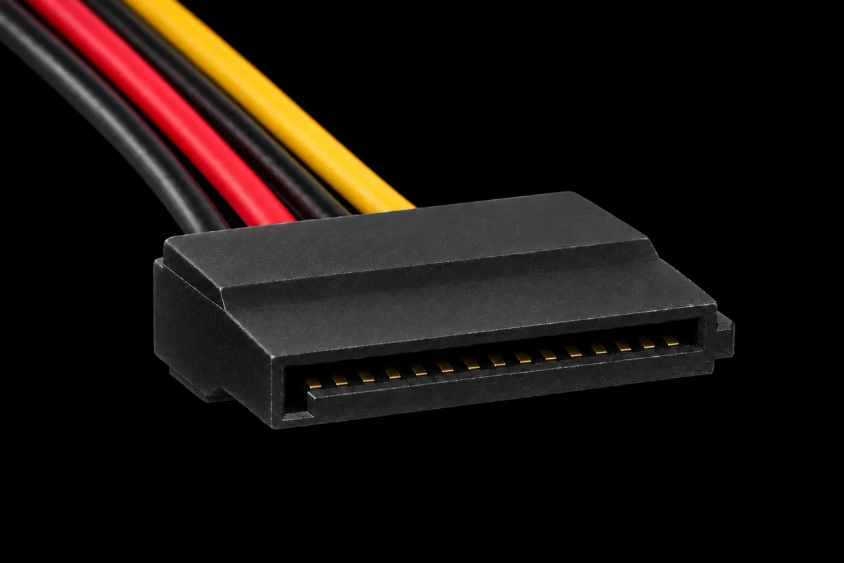
The flat SATA plug feeds drives and fan or lighting hubs. Fifteen contacts sound like a lot, but there are only three voltages: +3.3 V, +5 V and +12 V, three contacts each, plus grounds. The contacts are tiny, so each voltage uses three in parallel.
- Made for hot-swap bays. Drive datasheets show contacts of different lengths: ground first, then precharge, then the remaining power. That supports hot swapping in systems designed for it; in an ordinary PC, shut down and unplug before changing drive cables.
- 3.3 V is optional now. Intel: "+3.3V DC is removed from SATA V3.2 spec. but it is recommended if there is backward compatibility concern."
The pin 3 trap. Newer SATA revisions turned pin 3 into PWDIS, a power-disable input for data-centre drives. Western Digital documents it: on drives with Power Disable, voltage on pin 3 can hold the drive off. TrueNAS users report isolating that pin as a workaround for drives taken out of external enclosures. Check your exact drive and use a compatible power connection.
"Molex to SATA, lose all your data." Builders use this saying to warn about cheap Molex-to-SATA adapters, especially injection-moulded ones. It is not a safety test of every adapter: the safest choice is a power cable approved for your supply.
Molex and floppy: the veterans
| Peripheral 4-pin ("Molex") | Floppy 4-pin ("Berg") | |
|---|---|---|
| Pin 1 | +12 V (yellow) | +5 V (red) |
| Pins 2–3 | ground | ground |
| Pin 4 | +5 V (red) | +12 V (yellow) |
| Pitch | 5.08 mm | 2.5 mm |
| Status | still on new supplies | Intel: "Do Not Include (For Historical Reference Only)" |
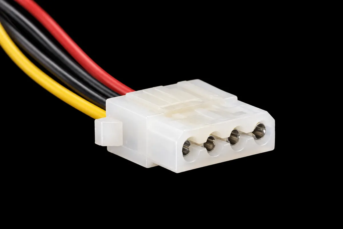
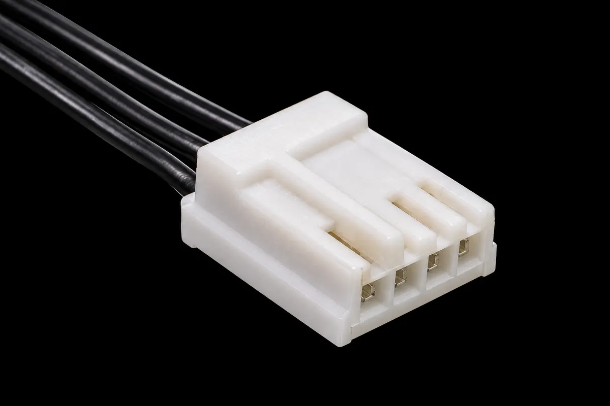
Did you know? Everyone calls it Molex, but Intel's guide lists it as "AMP 1-480424-0 or Molex 15-24-4048": both companies make it. Its pins float in their holes to self-align, which is why it is famously hard to plug in.
ATX12VO: when the supply only makes 12 V
In 2019 Intel published ATX12VO: the power supply makes only 12 V and the motherboard creates its own 5 V and 3.3 V. Gamers Nexus explains the motive: lower idle power for stricter energy rules. The 24-pin plug becomes a 10-pin one (Intel ATX12VO design guide, table 5-2):
| Pin | Signal | Pin | Signal |
|---|---|---|---|
| 1 | PS_ON# | 6 | PWR_OK |
| 2 | ground | 7 | +12 V standby |
| 3 | ground | 8 | +12 V |
| 4 | ground | 9 | +12 V |
| 5 | I_PSU% (load in %) | 10 | +12 V (+ sense wire) |
- Intel rates it at 216–288 W (6–8 A per contact); bigger boards add an extra connector.
- SATA drives get their 5 V from small headers on the motherboard.
- The standby rail is 12 V, not 5 V, so an ordinary supply cannot be adapted with wires alone. Users on the Linus Tech Tips forum describe a Corsair adapter cable (CP-8920272) with a small 5-to-12 V converter inside.
Modular cables do not mix
On a modular supply the cables also unplug at the supply end. The device end follows the standards above; the supply end follows none, and every brand, sometimes every model line, wires it differently.
- A cable from another supply may fit perfectly and still put 12 V where a drive expects 5 V.
- Builders on Reddit's r/buildapc warn, from experience: never reuse modular cables from another supply.
- Use the cables that came in the box, or ones the manufacturer lists as compatible.
Before ATX: AT P8/P9 and the AUX plug
The IBM PC/AT of 1984 powered its motherboard through two identical 6-pin plugs side by side (IBM Technical Reference, page 1-57):
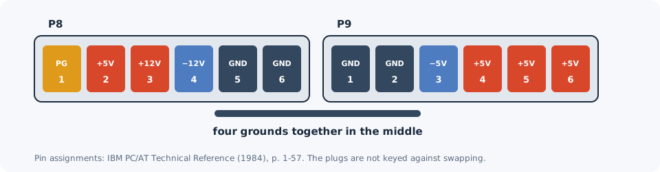
- Nothing stopped you from swapping them, and a swapped pair put the wrong voltages on the board. Technicians learned the rule "black wires together".
- AT supplies had no soft power: the front power switch carried mains voltage.
ATX replaced both plugs in 1995. For a few years demanding boards also took an ATX AUX 6-pin plug, added in ATX 2.02 and recommended in ATX 2.03 (1998) for "250 W and 300 W configurations": three grounds, two 3.3 V and one 5 V. It disappeared when processors moved to their own 12 V plug.
Myths and facts
| Myth | Fact |
|---|---|
| "The 8-pin PCIe plug has more +12 V wires than the 6-pin." | Same three +12 V contacts; the extra pins are a ground and a sense line. |
| "A 6+2 plug is weaker than a solid 8-pin." | Same contacts, same 150 W; the split only adds compatibility. |
| "The empty hole in my 24-pin cable is a defect." | Pin 20 is Reserved; it once carried −5 V. |
| "A 600 W cable pushes 600 W into the card." | The SENSE pins only set a limit; the card draws what it needs. |
| "12V-2x6 needs a new cable." | The change is in the header on the card and supply; 12VHPWR cables fit. |
| "If a modular cable fits, it is compatible." | Supply-side pinouts are not standardised. |
Safety checklist
- Never open a power supply. The cables carry 12 V or less, but inside the box mains is turned into several hundred volts stored in large capacitors that can stay charged after unplugging.
- Testing a supply. The green PS_ON# line is what a power-supply test jumper uses, but this article is not a test procedure: follow your supply maker's instructions for your exact model.
- Never force a plug. If it does not slide in, it is probably the wrong one.
- Do not mix modular cables from different supplies.
Sources
Primary documents
- Intel ATX 3.0 Multi-Rail Desktop Platform Power Supply Design Guide (336521): main, CPU, PCIe, SATA and peripheral connectors; 12V-2x6 power limits.
- Intel ATX12VO Desktop Power Supply Design Guide, revision 2.11: ATX12VO 10-pin; 12V-2x6 pinout and header changes.
- Intel ATX Specification 2.03 and 2.01: 20-pin plug, −5 V, PS_ON#, AUX connector.
- IBM Personal Computer AT Technical Reference (1984): P8 and P9.
Manufacturer guidance
- NVIDIA: 12VHPWR connector update (November 2022)
- Western Digital: Power Disable pin
- Seasonic: high-power graphics card cabling
- Corsair: do I need both CPU power cables?
- ASUS: modular PSU cables
Reviews, press and community